Environmentally Non-Disturbing Under-ice Robotic ANtarctiC Explorer: Hovering Autonomous Underwater Vehicle
During the past six years Stone Aerospace has developed two generations of autonomous underwater vehicles and used them in a wide variety of hazardous environments from the original exploration and mapping of deep hydrothermal springs to sub-glacial lake exploration and science missions in Antarctica. ENDURANCE (Environmentally Non-Disturbing Under-ice Robotic ANtarctiC Explorer), our second-generation AUV, represents a major re-design of the DepthX vehicle to accommodate a sub-ice mission to West Lake Bonney in Taylor Valley, Antarctica (See Figure 1). The scientific objectives of the mission are to:
- Characterize the aqueous chemistry of the lake in full 3D via automated sub-ice sonde casts
- Create a high resolution 3D map of the underwater interface between Taylor Glacier and West Lake Bonney and, if possible, to image the underwater portion of the glacier face
- Create a high resolution bathymetric map of the lake floor
- Do all of this when deployed down a melt hole through 3 meter thick ice cap barely larger in diameter than the vehicle, to ranges as far as 700 meters or more in radius from the melt hole and return home safely following each mission
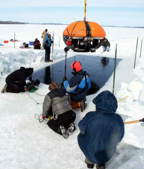
Figure 1: The Endurance AUV during the preliminary sub-ice tests in Wisconsin. The Wisconsin tests were a part of the pre-qualification of systems for use in ice-cold water and under-ice navigation prior to deployment to Antarctica in November and December of 2008.
Navigation
We added two new navigation systems to the vehicle to supplement the dead-reckoning and SLAM navigation originally used on DepthX. The first of these is a mid-range inverted USBL (Ultra Short BaseLine) system that is used for navigation correction when the vehicle is within a 300 meter radius of the melt hole (Figure 2).
The iUSBL data runs through a Kalman filter for deep and mid-range navigation. Upon return to the proximal locus of the melt hole at the conclusion of a mission, then a fourth navigation system takes control. A proprietary system was developed in which the vehicle, looking through a zenith-facing camera located directly above the center of the robot (Figure 3), locks onto an optical guide beam that is centered in the melt hole. Once it confirms that this is a unique signal, the vehicle centers itself on the beam and rises up through the melt hole to the surface. Both systems were developed and tested in 2008 and were successfully deployed at Lake Bonney in November-December of 2008.
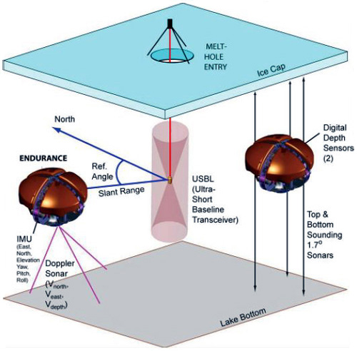
Figure 2: New navigation systems for Endurance include a mid-stage iUSBL. This instrument enables vehicle-determined slant range and heading estimates to a melt hole through thick ice cap.
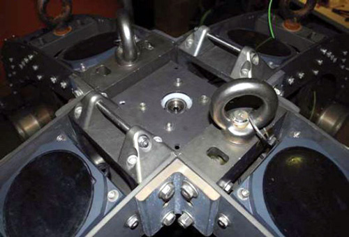
Figure 3: Zenith-pointing machine vision camera. We developed a proprietary homing stage machine vision algorithm to detect the centerline of the 3 meter deep x 2.5 meter-diameter hole that had been melted through the permanent ice cap of West Lake Bonney. The primary navigation filter passes control to the machine vision stage when the vehicle is considered to be within a 5 meter radius of the hole. The machine vision algorithm then centers the vehicle while simultaneously instructing controlled vertical motion until the vehicle surfaces. This is a fully autonomous behavior. (See a short video of this in one of our field reports.)
ENDURANCE Onboard Sensors and Payloads
We have equipped Endurance with a large array of tightly integrated systems and sensors. It has 96 sensors including scores of discrete tight beam obstacle avoidance and SLAM discrete sonar transducers; a multi-beam mapper; doppler velocity sonar; bottom altimetry sonar; redundant depth sensors; accelerometers, ring laser gyros, iUSBL transceiver; 16 different water chemistry sensors; and four real-time camera systems. Overall, ENDURANCE contains 45 computer processors that independently handle sensing, actuation, propulsion, situational awareness, obstacle control, vehicle “health”, communications, and a host of programmable mission behaviors. More than 200 meters of underwater cable, 10 pressure housings, and 145 underwater electrical penetrators make up the electronics interconnect system, all of which is contained inside the protective external ellipsoid.
Science Payload
Endurance’s science payload is a multi-purpose “Profiler” that spools out an instrument package, the sonde, from the vehicle to investigate water chemistry and other phenomena below the robot, where it may be unsafe or environmentally unfavorable to maneuver. Figures 4a and 4b show the sonde package and servo spooler used for the Lake Bonney mission. The sonde pays out on a custom 10/100 ethernet and power cable that can descend as much as 100 meters below the vehicle.
Figures 5a-d show sonde deployment from pre-Antarctic Endurance tests at NASA’s Neutral Buoyancy Lab. During the West Lake Bonney missions in Antarctica this profiler allows the vehicle to autonomously sample water chemistry through a series of pristine stratified water layers while the vehicle “ice picks”, stabilizing itself against the ice ceiling above it, in a fresh water lens under the ice cap, thus not disturbing the medium to be measured. A stand-off altimeter then stops the descent for each sonde profile at 1 meter above the lake bottom to avoid disturbing the bottom sediment. It then takes high resolution photos and retracts to the vehicle for maneuvering while the vehicle proceeds to the next drop point.
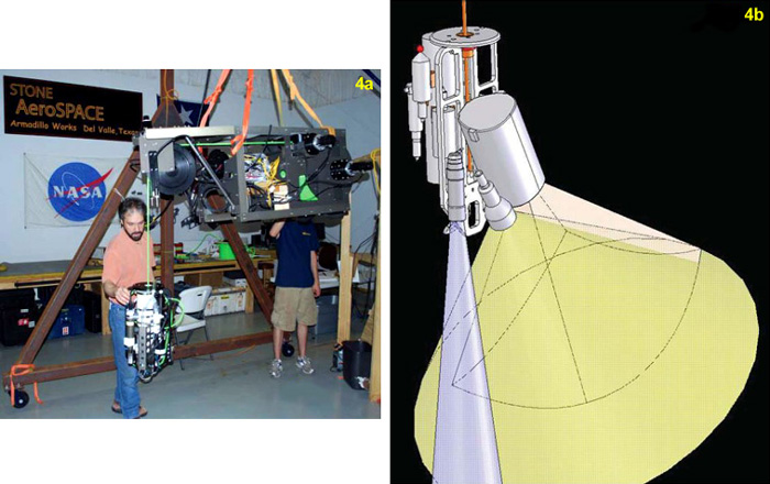
Figure 4: Endurance Profiler System. 4a) The Profiler science payload with the sonde deployed during the initial fabrication and testing of the system at Stone Aerospace; 4b) A computer-generated model showing the sonde components. These include 9 aqueous chemistry sensors, bottom standoff altimeter, video camera, lights and 10/100 ethernet data and power cable.
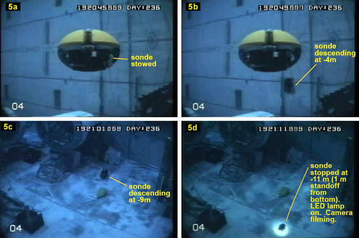
Figure 5: The Profiler in action at the Neutral Buoyancy Lab at Johnson Space Center. 5a) The vehicle maneuvers to the sonde grid points and hovers in “station keeping” mode. 5b) The sonde then begins its descent. 5c) The sonde at 8 m depth. 5d) The sonde stops at 1 m bottom altimeter standoff, then powers on the sonde light. Then it takes a few seconds of high-def video before returning to its stowed position on the vehicle.
Onboard Power and Propulsion
We designed Endurance to be fully redundant. It contains four horizontal thrusters and two vertical thrusters. Any two horizontal and one vertical thruster pair can maneuver the vehicle. Similarly, the system contains two independent power supplies. The current battery upgrade program in summer 2009 will boost vehicle range to more than 5 kilometers of powered flight. Combined, the six thrusters can generate more than 1400 N of directed thrust. The vehicle can “station keep”, or hover, within a precision of 5 cm horizontally and 1 cm vertically. In addition, it can repeatedly return to pre-defined geo-referenced locations.
Field Operations and Operating Modes
Although ENDURANCE is fully autonomous, we frequently operate it with a fiber optic data link (a 0.9 mm diameter glass fiber) so that scientific operations can be monitored by a team of experts in real-time. Mission control is portable, typically consisting of four large flat screen monitors and twin laptop projectors. This is all tied into the live high-bandwidth data feed coming from the vehicle. We use a GUI-driven mission planner to define the general parameters of mission. Low level “behaviors”, such as obstacle avoidance, situational awareness, wall following, proximity operations, and other goal states take precedence over generalized scripting.
Figure 6 shows a typical high level scripted mission. A bathymetric map of a lake was desired and the vehicle was given a raster-scan script. Within power and obstacle-avoidance allowed parameters, the vehicle would continue to execute this function until it scanned the entire lake, without knowing its external geometry in advance.
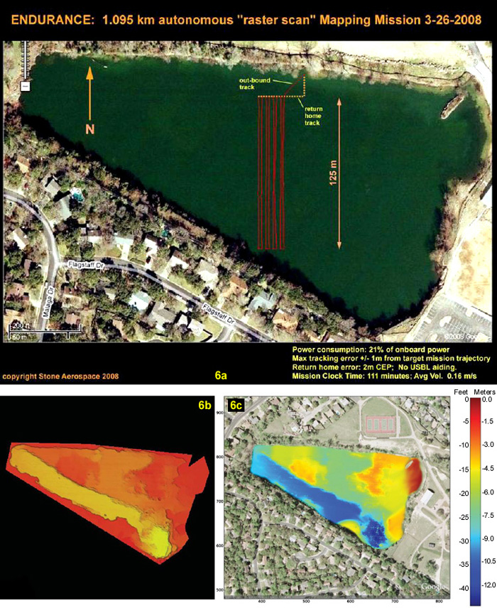
Figure 6: Bathymetric scanning tests for Endurance. These tests, using both dead reckoning and fused iUSBL navigation solutions, were one step along the path to mapping West Lake Bonney in Antarctica in December 2008. 6a) An overview of raster scanning the Hyde Park Quarry in Austin, Texas. 6b) This stand-alone 2-1/2D plot was then the resulting high resolution map. 6c) The aerial image of the quarry with the data superimposed.
For more details on the Endurance mission to West Lake Bonney, see our field blogs.